How to Install the Clutch Sense Wire for the ECU Stutterbox Modification
![[NOTE!]](/g/note!.gif) This modification is only intended to
be used in conjunction with the Technomotive Stutterbox Modification for drag
racing. The modification described below will add absolutely no benefit to a
stock ECU. Besides, you need our special wire!
This modification is only intended to
be used in conjunction with the Technomotive Stutterbox Modification for drag
racing. The modification described below will add absolutely no benefit to a
stock ECU. Besides, you need our special wire!
Introduction.
The Technomotive Stutterbox Modification gives the ECU three different
redlines (the RPM at which the ECU will kill fuel and spark to the engine):
- With the clutch out, the redline is the stock 7500 RPMs (or we can up that
all the way to 8500 if you so desire).
- With the clutch in, the redline lowers to 6000 RPMs (or whatever you like).
This allows the engine speed to drop when you push the clutch in to make a
shift, leaving you free to leave the throttle pressed to the floor. This
bypasses the need for a blow-off valve while drag racing, since the throttle
never closes.
- With the clutch in, but the car completely stopped, the redline becomes
4500 RPMs (or whatever you like). Now you can "set and forget" your
launch RPMs at the line and concentrate on hitting a perfect light.
So, in order for this modification to be successful, the ECU has to know
when the clutch is depressed. As shipped from the factory, however, the ECU has
no idea about the clutch position. The switch that kills the starter unless the
clutch is depressed actually only affects the starter and not the ECU.
How do we get around this? Well, the manual tranmission versions of the
cars have an unused input that is normally connected to the Park/Neutral
indicator switch on an automatic. We will give that formally unused pin a new
use and hook it up to the clutch starter kill switch!
Figure 1
Engine
Computer Location
- Locate the ECU. Figure 1 shows
the ECU in the center console, underneath the radio. To get to the Figure
2 views below, you will have to remove the center console carpeted kick
panels from both the driver and passenger sides.

Figure 2
Connector
Release Tabs
- Unplug the ECU. Figure 2 is a
view of the ECU if you could see the front of it using x-ray vision from the
front bumper. Note that the connectors have release-tabs pointed towards the
front of the car. It is a bit difficult to figure out how to get the plugs
pulled at first, so go slowly and wiggle the plugs out carefully. You might
find it easier to skip to the next step and remove the plugs after the ECU bolts
have been removed.

Figure
3a
Driver side |

Figure
3b
Passenger side |
- Unbolt the ECU.Figure 3a is a
picture from the driver side and Figure 3b is a picture from
the passenger side (your views might be slightly different depending upon stereo
equipment options installed). The passenger side picture shows a lot of wires
that were added for a rallye computer that most likely won't be in your car.

Figure 4
Sliding
the ECU out
- Remove the ECU. First, shake the ECU a bit to get
it off the notch tabs. Then, slide the ECU out as show in Figure 4.
There are three bolts that hold the ECU in place (circled in yellow). When
removing the ECU, you might have to wiggle it around a bit - there are other
wiring harnesses in the area, making for a tight squeeze.

Figure 5
Unhooking
the Tie-Down
- Unlatch the ECU harness. First, remove the lower
side-cover on the passenger side. This is not shown in Figure 5,
unfortunately, because it has already been removed from the picture. Anyway,
this side-cover has only one large brass colored Phillips screw holding it in.
It then will slide off of a rod-like extension near the firewall. (This sounds
a lot more complicated than it actually is.) Next, you must unlatch the harness
tie-down as shown in Figure 5. This will give better access
to the ECU input we are attempting to tap into.

Figure 6
Pulling
out the Harness
- Expose the ECU harness. This is just as easy as it
sounds. Pull out the three-plug harness and arrange it as show in Figure
6. Please note that the plug keeper tabs are pointing up (towards the
camera). We will be tapping into the smallest of the three plugs.

Figure 7
Pin
104 of the ECU
- Cut the Park/Neutral wire on the ECU. Pin 104 is
the Park/Neutral input. As clearly shown in Figure 6, pin
104 is connected to a black wire (which of course means ground). Peel back the
black electrical tape on the harness a couple inches for some working space.
Then cut the wire about 1½ inches back from the plug.

Figure 8
Applying
the Vampire
- Connect the Clutchwire to the ECU input. The
picture in Figure 8 got a little washed out, so the black wire
has been highlighted with a white border for better visibility. The "vampire"
is a simple device that allows you to quickly connect two wires together without
stripping and soldering them. We have provided vampires in the clutchwire kit -
however, we recommend soldering all the connections if you have the means to do
so.
There are two ends (of course) to the clutchwire in the kit. The end
with only one wire is the one which gets attached to the ECU.
Slip both
wires into the vampire device. Press the metal clamp down in the center as hard
as you can with your hand - you might have to wiggle it to get the wires to
center in the device. When you are sastified that the clamp is coming down even
around both wires, use a pliers to fully shove the metal clamp in. Then fold
the plastic flap over to protect and hold in the metal clamp.
At this point,
we recommend dressing the vampire using electrical tape to fasten it to the
small plug harness. Then toss the rest of the wire under the dash and into the
driver footwell.

Figure
9
Identifying the Clutch Switch
- Find the clutch switch. This part is difficult, as
you need to be lying on your back in the driver footwell in order to see the
clutch switch. Once you get your head down there, you will see the view in
Figure 9. The clutch switch is easily identified by the short
blue and black wires leaving it and terminating in a connector. On the other
side of this connector are a black and green wire. We are very interested in
the green wire.
To make your life easier, pull the connector off of the
metal hanger it is on. This might take a bit of coaxing. Once the connector is
pulled, press on a small tab to separate the two halfs. Pull the half with the
green wire down as far as possible. You might have to loop through a couple
harnesses to get more length out of it.

Figure
10
Cutting the Clutch Switch Wire
- Cut the clutch switch wire. From the previous
step, the connector plus wire should be hanging down as low as in Figure
10. You might have to peel back a layer of electrical tape to expose
about 3-4 inches of wire. Remember, the green wire is the wire we are
interested in. As before, cut the wire about 1½ inches away from the
connector.

Figure 11
Identifying
the Clutchwire
- Identify the two ends of the clutchwire. Figure
11 pretty much explains it all.
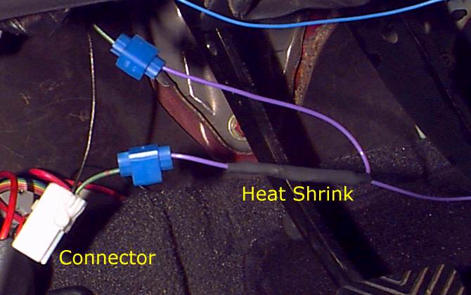
Figure
12
Attatching the Clutchwire
- Attatch the clutchwire to the clutch switch connector.
Figure 12 again shows the heat shrink side of the clutchwire
attatched closest to the connector. Apply the vampires (or solder the
connections) in the same way as was done above in step #8. At this point, the
ECU is now modified to be able to see clutch position.
- Final steps. Now would be a good time to dress up
the wire so the it won't interfere with your pedals. You can shove it down
underneath the edge of the carpet in the driver footwell. If you want to
quickly test the modification without having to put the ECU back in the proper
spot, you can simply plug the ECU in and leave it laying in the passenger
footwell until you are done with testing.
©1997 Technomotive
September
17th, 1997